DATASHEET
PRODUCT DESCRIPTION
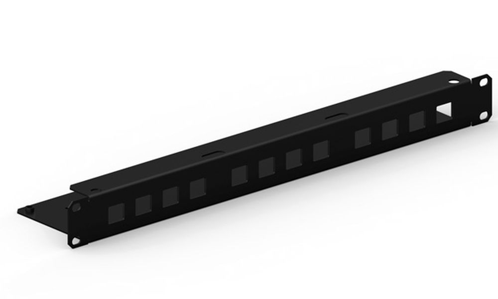
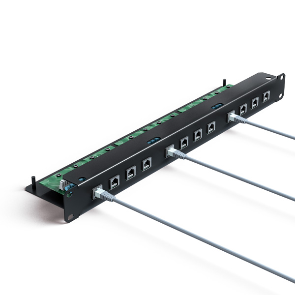
ATLAN 12 CAT6 - Surge protector for category 6 computer networks. 1 GBit/s. RJ45 input/output connectors.UC2 test (2kA/4kV). Up = 150V. Includes 12 cables (CAT6) with RJ45 connectors, 0,5 m long and 19'' rack.
ATLAN protectors are especially designed to prevent failures in data transfer between equipment within the same network. They protect the electronic circuit inputs of the network cards against damage due to transient currents.
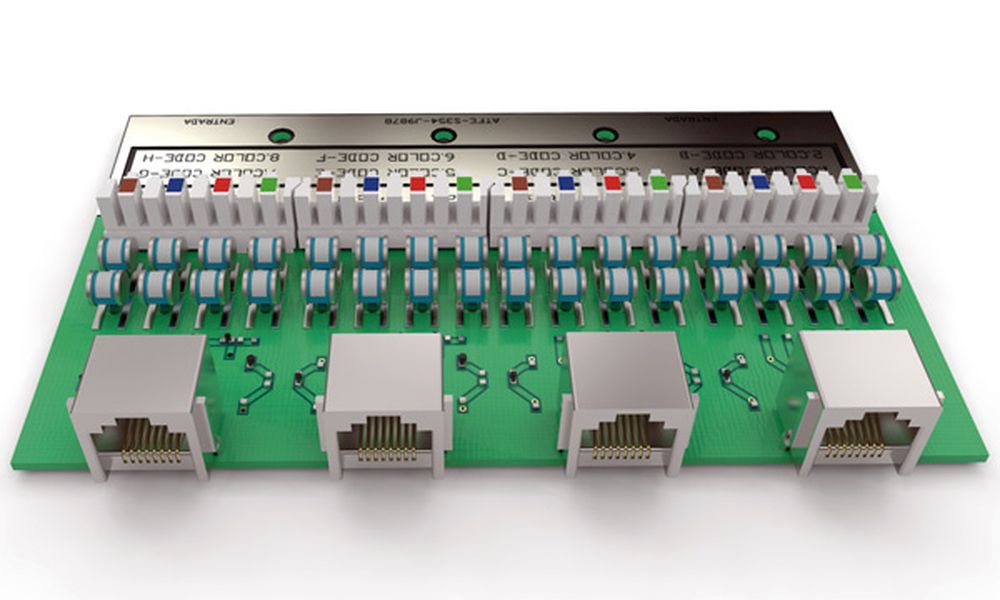
ATLAN 12 is an SPD for 12 protected lines, with four pairs protected per line. This is done with a printed circuit board with crimped input cable and RJ45 output connector, able to withstand current up to 2 kA for each line and with a transfer speed of 250 MHz.
It is especially designed to be inserted into a rack and protect computer network distribution cabinets. Due to its high transfer speed, it is suitable for networks transferring a large amount of data (servers, workstations, graphic stations etc.)
Includes 50 cm category 6 output cable already.
Tested in official and independent laboratories, obtaining their characteristics according to relevant standards (shown in the table).
DATASHEET
| Reference | AT-2211 |
| Maximum transfer speed | 1000 Mbit/s |
| Nominal voltage (Un) | 5 VDC |
| Maximum continuous operating voltage (Uc) | 25 VDC |
| Nominal discharge current per line C2 (In (C2)) | 2 kA |
| Protection level at In(8/20 µs wave) (Up(In)) | 150 V |
| Maximum operating current (IL) | 300 mA |
| Series resistance (Rs) | 11 Ω |
| Response time (tr) | < 10 ns |
| Working temperature | -40 °C to +70 °C |
| Protector location | Indoor |
| Type of connection | Series (two ports) |
| Nr. of pairs protected | 12 x 4 pairs |
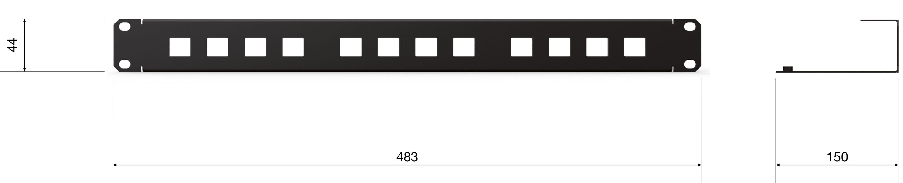
| Dimensions | 483 x 150 x 44 mm |
| Enclosure material | Steel |
| Enclosure protection | IP20 |
| Input / output connector | Crimped connector / RJ45 |
| Earthing system | Screw M5 |
TESTS AND CERTIFICATIONS
Certificated tests according to: UNE-EN IEC 61643-21
Relevant standards: UNE 21186, NF C 17-102, IEC 62305
Products compliant with EC requirements.
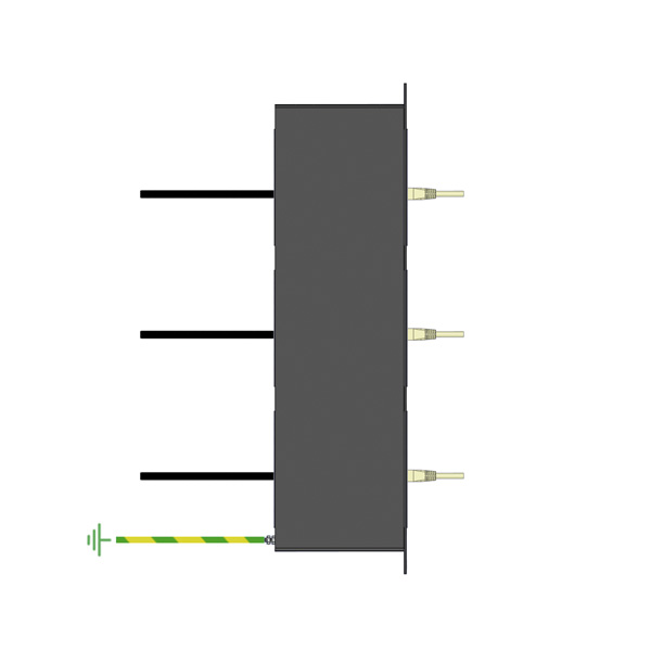
Diagram (mm)
INSTRUCTIONS
INSTALLATION
Protection should be installed as close as possible to the equipment. In this particular case, we're talking about switches and hubs.
If there are two pieces of equipment located in separate buildings but linked together, the protection must be installed on both sides of the line.
The recommended procedure for installation is the following:
- Screw the protectors onto the 19" rack for computer network distribution.
- Run the network distribution lines from the hub or switch to the protector.
- Bond the rack ground to the ground marked in the box chassis.
SAFETY AND MAINTENANCE
Connection to earth is a must. Earthing in the whole installation must be bonded either directly or by a spark gap and resistance should be lower than 10 Ω.
If the indications on this datasheet are not fulfilled during use or installation of the protectors, the protection provided by this device could be compromised.