DATASHEET
PRODUCT DESCRIPTION
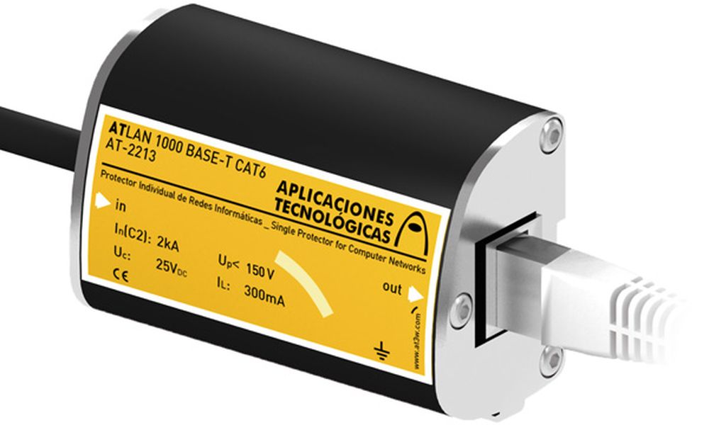
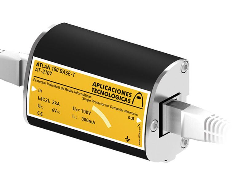
ATLAN 100 BASE-T - Surge protector for 100 MBits/s computer networks in a metallic enclosure. RJ45 input/output connectors. C2 Test (2kA/4kV). Up = 100V. Includes RJ45 cable, 0,5 m long.
ATLAN protectors are especially designed to prevent failures in data transfer between equipment within the same network. They protect the electronic circuit inputs of the network cards against damage due to transient currents.
ATLAN is a protector with RJ45 input and output, able to withstand current up to 2 kA per line.
It is designed to individually protect every individual piece of equipment connected to the computer network.
Includes 50 cm cable with RJ45 connector.
ATLAN series protectors have been tested in official and independent laboratories, obtaining their characteristics according to relevant standards.
DATASHEET
| Reference | AT-2107 |
| Maximum transfer speed | 100 Mbit/s |
| Nominal voltage (Un) | 5 VDC |
| Maximum continuous operating voltage (Uc) | 6 VDC |
| Nominal discharge current per line C2 (In (C2)) | 2 kA |
| Protection level at In(8/20 µs wave) (Up(In)) | 100 V |
| Maximum operating current (IL) | 300 mA |
| Series resistance (Rs) | 15 Ω |
| Response time (tr) | < 10 ns |
| Working temperature | -40 °C to +70 °C |
| Protector location | Indoor |
| Type of connection | Series (two ports) |
| Nr. of pairs protected | 4 pairs |
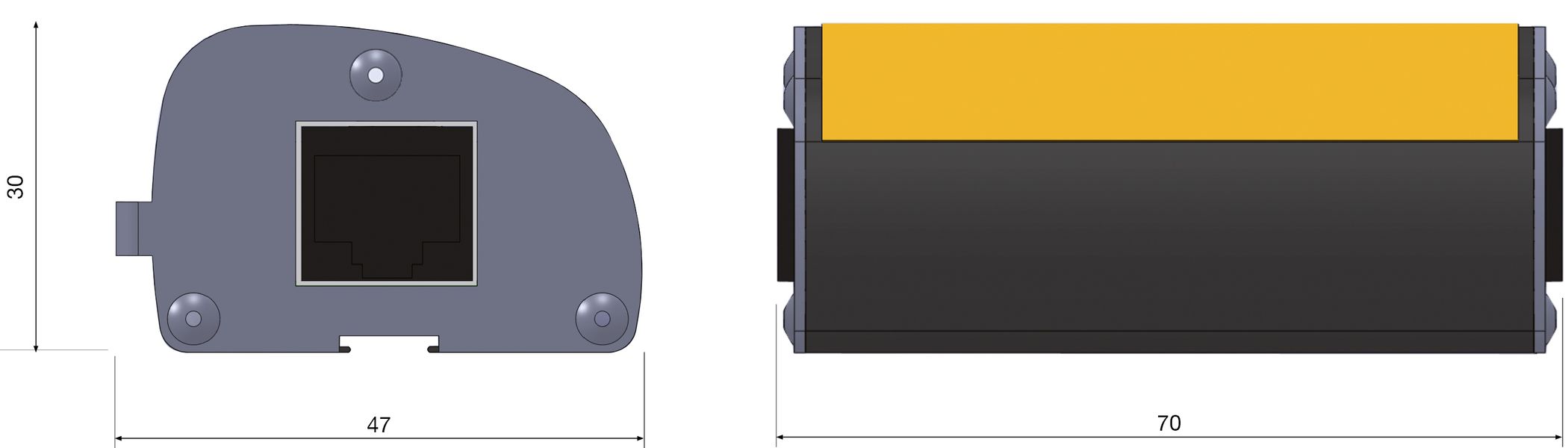
| Dimensions | 68 x 47 x 30 mm |
| Enclosure material | Aluminium |
| Enclosure protection | IP20 |
| Input / output connector | RJ45 / RJ45 shielded |
| Earthing system | 6 mm faston |
TESTS AND CERTIFICATIONS
Certificated tests according to: UNE-EN IEC 61643-21
Relevant standards: UNE 21186, NF C 17-102, IEC 62305
Products compliant with EC requirements.
Diagram (mm)
INSTRUCTIONS
INSTALLATION
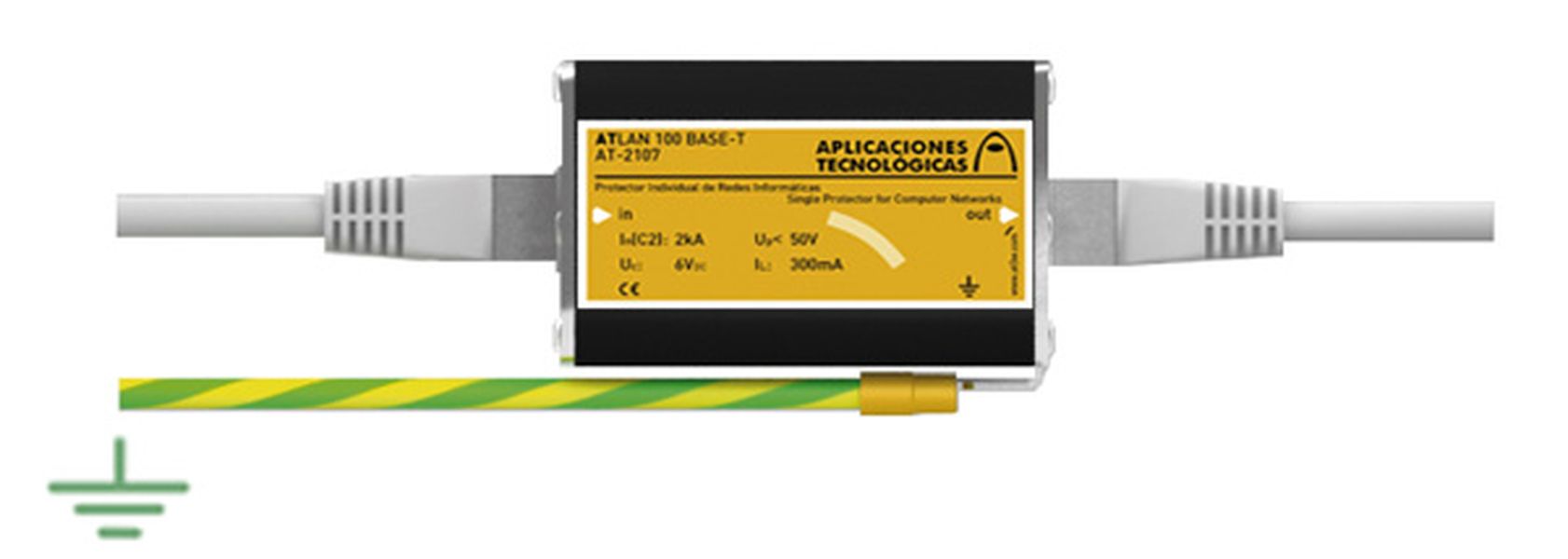
Protection should be installed as close as possible to the equipment. A UTP cable with a RJ45 connector has 8 wires. ATLAN protects 4 pairs (8 wires) in series.
If there are two pieces of equipment located in separate buildings but linked together, the protection must be installed on both sides of the line.
The recommended procedure for installation is the following:
- Insert the protector between the cable with RJ45 connector and the equipment to be protected.
- Bond the protector to the ground using the 'faston' type connector provided.
SAFETY AND MAINTENANCE
Connection to earth is a must. Earthing in the whole installation must be bonded either directly or by a spark gap and resistance should be lower than 10 Ω.
If the indications on this datasheet are not fulfilled during use or installation of the protectors, the protection provided by this device could be compromised.