


DATASHEET
PRODUCT DESCRIPTION
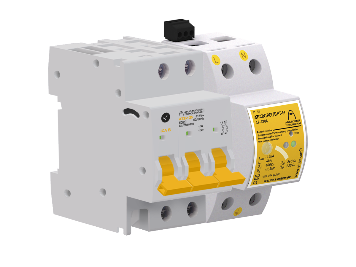
KIT ATCONTROL/B PT-M 6 - Kit with Single-phase protector against permanent and transient overvoltages, shunt release and MCB with nominal current In = 6A. Actuating time 275V→3-5s / 400V→0,1-0,2s. Imax(8/20) = 15kA. Up = 1,1kV.
KIT ATCONTROL protectors cut off the power supply when they detect a permanent overvoltage , (for example, a fault in the neutral), thus protecting the equipment installed downstream.
Moreover, they also actuate when they detect a transient overvoltage, driving the current to earth and reducing the voltage to a level that does not damage the connected equipment. Tested and certified as protector Type 2 in official and independent laboratories according to standard EN IEC 61643-11.
It has a test button to check that installation has been executed correctly.
This protector is self-configurable. It automatically detects the voltage and programmes the permanent overvoltage limits.
DATASHEET
DIMENSIONS
| Protector dimensions | 36 x 90 x 80 mm |
| Number of DIN modules (DIN 43880) of the protector | 2.00 |
| Element 1 | Circuit breaker + shunt release |
| Dimensions of the element 1 | 51 x 81 x 65 mm |
| Number of DIN modules (DIN 43880) of the element 1 | 3.00 |
ELECTRICALS
| Nominal current | 6 A | |
| Type of line | Single-phase | |
| Maximum short-circuit current | 6 kA | |
| Nominal voltage for the shunt release | 110-415 VAC / 110-250 VDC |
Configuration A
| Nominal voltage (L-N) | Un | 230 V |
| Maximum overvoltage (L-N) | Uc | 400 V |
| Actuation voltage V1 (L-N) | Ua | 275 V |
| Actuation time at V1 | 3-5 s | |
| Actuation voltage V2 (L-N) | 400 V | |
| Actuation time (V2) | 0,1-0,2 s |
Configuration B
| Nominal voltage (L-N) | Un | 120 V |
| Maximum overvoltage (L-N) | Uc | 400 V |
| Actuation voltage V1 (L-N) | Ua | 150 V |
| Actuation time at V1 | 3-5 s | |
| Actuation voltage V2 (L-N) | 230 V | |
| Actuation time at V2 | 0,1-0,2 s |
Protection against transient overvoltages
| Test type according to UNE-EN61643-11 | Type 2 | |
| Protection categories according to the REBT | I, II, III, IV | |
| Nominal discharge current (8/20 µs wave) | ln | 5 kA |
| Maximum discharge current (8/20 µs wave) | lmax | 15 kA |
| Protection level at In(1,2/50 µs wave) | Up | 1.10 kV |
CONSTRUCTION
| Type of connection | Parallel (one port) |
| Fixing | DIN Rail |
| Enclosure material | Polyamide |
| Insulation resistance | > 1014 Ω |
| Self-extinguishing enclosure | V-0 Type according to UNE-EN IEC 60707 (UL94) |
| Nr. of poles | 2 |
| Warning for permanent overvoltages | Warning light. Green light: correct mains voltage. Red: overvoltage |
| Warning for transient overvoltages | Warning mechanism. Yellow: protector status ok. Black: Replace |
ENVIRONMENTAL
| Working temperature | -5 to +40 °C |
| Protector location | Indoor |
| Enclosure protection | IP20 |
CONNECTION
Protector cables
| Minimum / Maximum section | 2,5 / 35 mm2 |
| Screw | Philips, H2 |
| Tightening | 3 N·m |
Activation cables (S1, S2)
| Minimum / Maximum section | 1 / 1,5 mm2 |
| Screw | DIN 5264, M 2 |
Cables of element 1
| Cables of element 1 | Circuit breaker |
| Minimum / Maximum section | 4 / 25 mm2 |
| Screw | Philips, H2 |
| Tightening | 3 N·m |
| Cables of element 2 | Shunt release |
| Minimum / Maximum section | 1 / 4 mm2 |
| Screw | Philips, H1 |
| Tightening | 1.20 N·m |
TESTS AND CERTIFICATIONS
Certificated tests according to the standard: UNE-EN IEC 61643-11
UNE-EN IEC 60898
UNE-EN 50550 (POP)
Relevant standards: UNE 21186, UNE-EN IEC 62305
Products compliant with EC requirements.
Diagram (mm)
INSTRUCTIONS
INSTALLATION
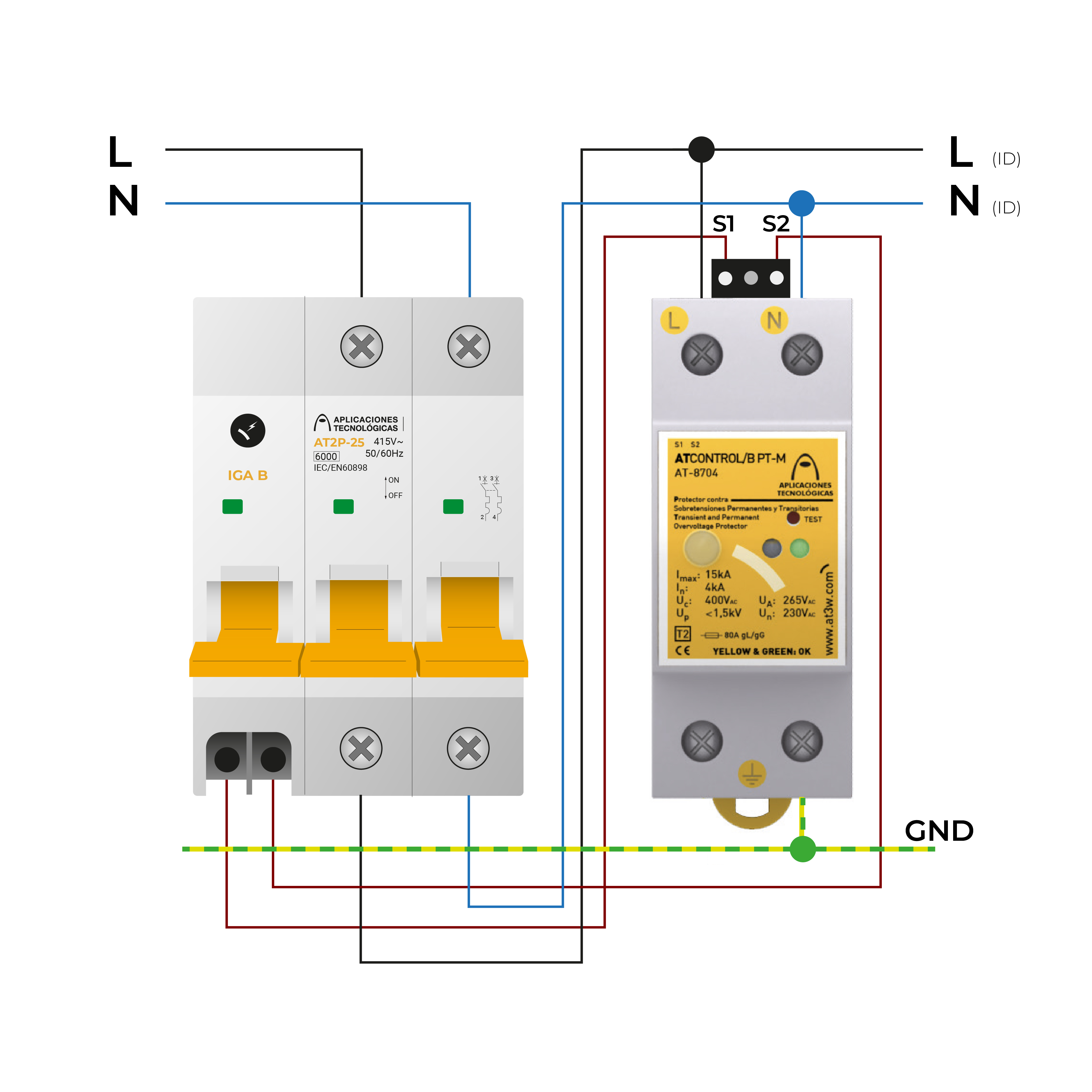
They must be installed in parallel with the low voltage supply line, downstream from the circuit breaker included in the kit.
The circuit breaker must be installed in series with the low voltage line, between the power control breaker (ICP) and the residual current breaker (ID).
Connect the S1 and S2 terminals, always without voltage, to the shunt release included in the kit.
SAFETY AND MAINTENANCE
Installation should be carried out without power in the line and can only be done by authorized professionals.
Connection to earth is a must.