DATASHEET
PRODUCT DESCRIPTION
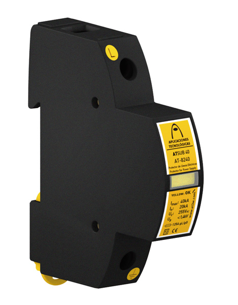
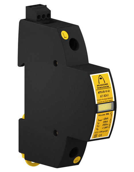
ATSUB-R 15-120 - Protector for power supply lines. Connection for remote warning. Single-pole. Type 2+3. Uc = 150 VAC. Imax =15 kA. Up(In) = 1200 V. Up(1,2/50) = 700 V. Size 1DIN.
Tested and certified as a protector Type 2+3 according to the standard EN IEC 61643-11.
Suitable for Categories I, II, III, IV according to ITC-BT-23.
Single-pole protection.
Containing zinc oxide varistors able to withstand very high currents.
Coordinable with protectors of series ATSHOCK, ATSHIELD and ATCOVER.
Short response time.
Does not produce deflagration.
Their activation causes no interruption in power supply.
Thermodynamic control device.
Voltage-free contact for the remote control.
ATSUB series protectors have been tested in official and independent laboratories, obtaining their characteristics according to relevant standards.
DATASHEET
ELECTRICAL
| Nominal voltage | Un | 120 VAC |
| Maximum continuous operating voltage | Uc | 150 VAC |
| Nominal frecuency | f | 50 - 60 Hz |
| Nominal discharge current per pole (8/20 µs wave) | In | 5 kA |
| Maximum discharge current per pole (8/20 µs wave) | Imax | 15 kA |
| Protection level for 8/20 µs wave at In | Up | 1200 V |
| Level protection for 1.2/50 µs wave | 700 V | |
| Protection level for 5 kA; 8/20 µs wave | 900 V | |
| Combined wave voltage | Uoc | 6 kV |
| Response time | tr | 25 ns |
| Backup fuse | 125 A gL/gG | |
| Maximum short-circuit current | 25 kA |
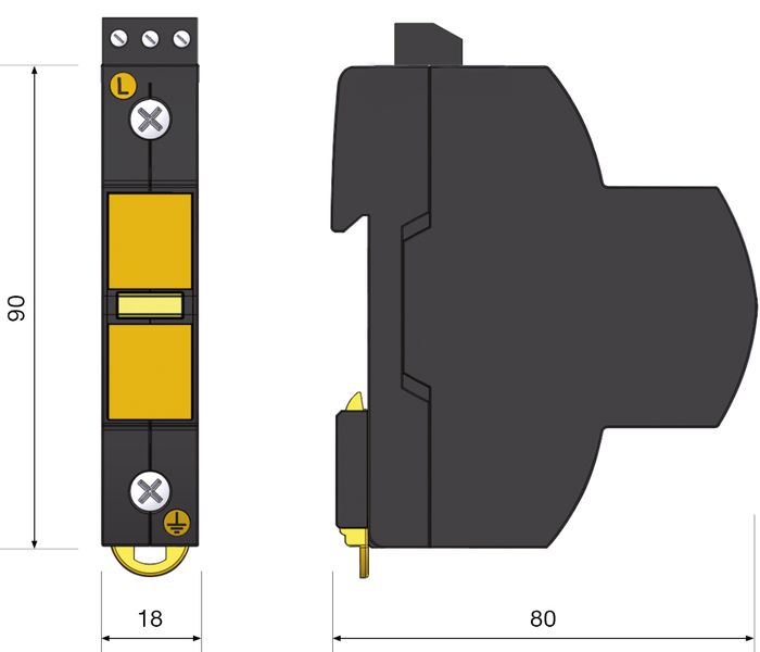
DIMENSIONS
| Length | 18 mm |
| Height | 96 mm |
| Width | 80 mm |
| Weight | 92 gr |
| Number of DIN modules (DIN 43880) | 1 |
ENVIRONMENTAL
| Working temperature | -40 °C to +70 °C |
| Protector location | Indoor |
| Enclosure protection | IP20 |
GENERAL
| Protection categories according to the REBT | I, II, III, IV |
| Test type according to UNE-EN61643-11 | Type 2+3 |
CONSTRUCTION
| Fixing | DIN Rail |
| Enclosure material | Polyamide |
| Insulation resistance | > 1014 Ω |
| Self-extinguishing enclosure | V-0 Type according to EN IEC 60707 (UL94) |
| Type of connection | Parallel (one port) |
| Nr. of poles | 1 |
| Warning | Warning mechanism. Yellow: protector status ok. Black: Replace. |
CONNECTION
| Minimum multi-stranded section | 4 mm2 |
| Maximum multi-stranded section | 35 mm2 |
| Minimum single-stranded section | 1 mm2 |
| Maximum single-stranded section | 35 mm2 |
| Screw | Philips H2 |
| Tightening | 3 N·m |
Voltage-free contact for the remote control
| Connection | Single-stranded /multi-stranded maximum section: 1.5 mm2 |
| Contact output | Switch |
| Operating voltage | 250 VAC |
| Maximum current | 2 A |
TESTS AND CERTIFICATIONS
Certificated tests according to EN IEC 61643-11.
Complies with requirements of UL 1449.
Relevant standards: NF C 17102, UNE 21186, EN IEC 62305.
Products compliant with EC requirements.
Diagram (mm)
INSTRUCTIONS
INSTALLATION
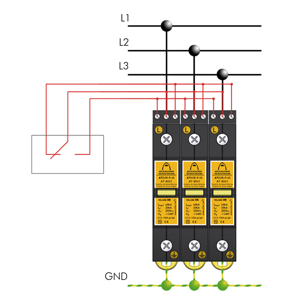
ATSUB surge protection devices must be installed in parallel with the low voltage power supply line.
When installed as medium protection, they should be separated from the coarse and/or tight protection by at least 10 metres of cable or, if this is not possible, by an ATLINK decoupling inductor, in order to achieve correct coordination between them.
Installation should be carried out without power in the line and can only be done by authorized professionals.
SAFETY AND MAINTENANCE
Connection to earth is a must. Earthing in the whole installation must be bonded either directly or by a spark gap and resistance should be lower than 10 Ω.
If the indications on this datasheet are not fulfilled during use or installation of the protectors, the protection provided by this device could be compromised.