DATASHEET
PRODUCT DESCRIPTION
IGA TEST T 32 PLUS - Three-phase protector against permanent overvoltages and undervoltages, with integrated MCB, nominal current 32A. Actuating time 275V -> 8-10s / 400V -> 0,1-0,2s: 80V -> 0,2s / 200V -> 0,8s.
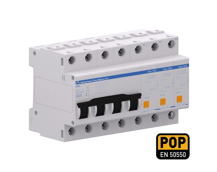
IGA TEST protectors cut off the power supply when they detect a permanent overvoltage or undervoltage, (for example, a fault in the neutral), thus protecting the equipment installed downstream.
The protector is formed by protective coils for permanent overvoltage linked to a miniature circuit breaker (MCB).
To restore the main circuit breaker, it is necessary to reconnect the protective coil in advance using the RESET button.
DATASHEET
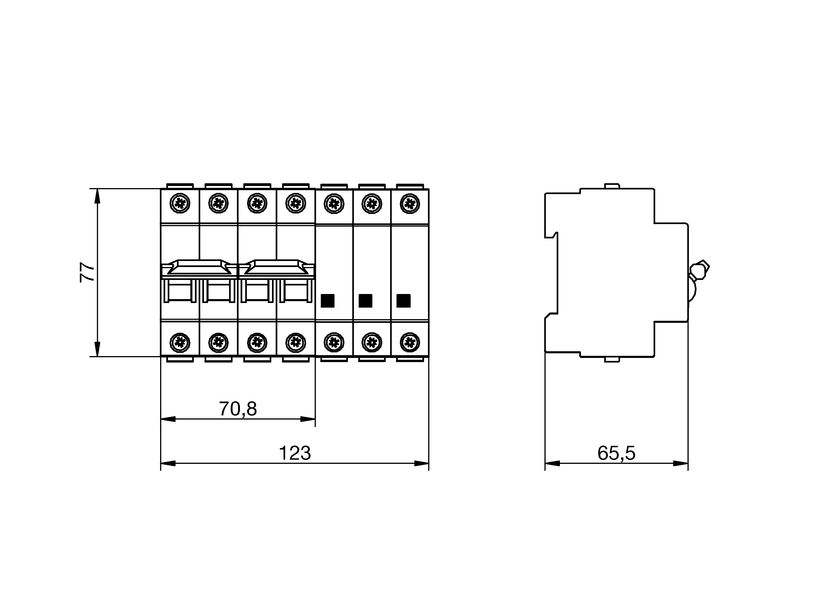
DIMENSIONS
| Protector dimensions | 123 x 81 x 65 mm |
| Number of DIN modules (DIN 43880) of the protector | 7.00 |
ELECTRICALS
| Nominal current | 32 A | |
| Type of line | Three-phase | |
| Maximum short-circuit current | 6 kA | |
| Nominal voltage (L-N) | Un | 230 V |
| Maximum overvoltage (L-N) | Uc | 400 V |
| Minimum operating voltage(L-N) | 80 V |
Working characteristics for overvoltages
| Actuation voltage V1 (L-N) | Ua | 275 V |
| Actuation time at V1 | 8-10 s | |
| Actuation voltage V2 (L-N) | 400 V | |
| Actuation time (V2) | 0,1-0,2 s |
Working characteristics for undervoltages
| Actuation voltage V1 (L-N) | Ua | 200 V |
| Actuation time at V1 | 0.8 s | |
| Actuation voltage V2 (L-N) | 80 V | |
| Actuation time at V2 | 0.2 s |
CONSTRUCTION
| Fixing | DIN Rail |
| Insulation resistance | > 1014 Ω |
| Self-extinguishing enclosure | V-0 Type according to UNE-EN IEC 60707 (UL94) |
| Nr. of poles | 4 |
ENVIRONMENTAL
| Working temperature | -40 to +70 °C |
| Protector location | Indoor |
| Enclosure protection | IP20 |
CONNECTION
Protector cables
| Minimum / Maximum section | 1,5 / 25 mm2 |
| Screw | Philips, H2 |
| Tightening | 3 N·m |
TESTS AND CERTIFICATIONS
Certificated tests according to the standard: UNE-EN IEC 61643-11
UNE-EN IEC 60898
UNE-EN 50550 (POP)
Relevant standards: UNE 21186, UNE-EN IEC 62305
Products compliant with EC requirements.
Diagram (mm)
INSTRUCTIONS
INSTALLATION
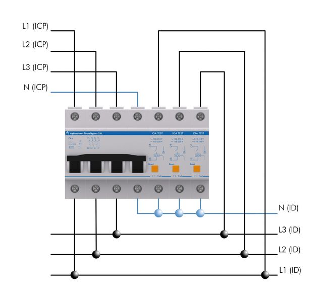
They must be installed in series with the low voltage line, between the Power Control Circuit Breaker (ICP) and the Residual Current Device (ID).
The protective coil must be installed between the line and the neutral, which connects to the residual current breaker (ID).
SAFETY AND MAINTENANCE
Installation should be carried out without power in the line and can only be done by authorized professionals.
Connection to earth is a must.